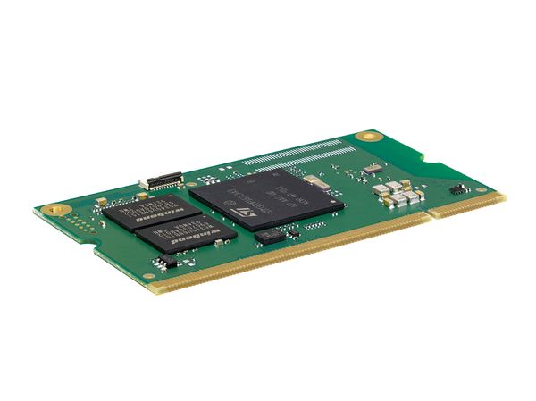
DHCOM STM32MP1-D2: Difference between revisions
From Wiki-DB
Jump to navigationJump to search
Ageisreiter (talk | contribs) |
Ageisreiter (talk | contribs) |
||
| Line 59: | Line 59: | ||
* [[media:PCN_DHCOM-STM32MP1-001_R01_2020-10-29.pdf|PCN_DHCOM-STM32MP1-001_R01_2020-10-29.pdf (high speed microSD switch EOL)]] | * [[media:PCN_DHCOM-STM32MP1-001_R01_2020-10-29.pdf|PCN_DHCOM-STM32MP1-001_R01_2020-10-29.pdf (high speed microSD switch EOL)]] | ||
* [[media:PCN_DHCOM-STM32MP1-002_R01_2021-12-23.pdf|PCN_DHCOM-STM32MP1-002_R01_2021-12-23.pdf (microSD socket EOL)]] | * [[media:PCN_DHCOM-STM32MP1-002_R01_2021-12-23.pdf|PCN_DHCOM-STM32MP1-002_R01_2021-12-23.pdf (microSD socket EOL)]] | ||
* [[media:PCN_DHCOM-STM32MP15-003_R01_2023-05-22.pdf|PCN_DHCOM- | * [[media:PCN_DHCOM-STM32MP15-003_R01_2023-05-22.pdf|PCN_DHCOM-STM32MP15-003_R01_2023-05-22.pdf (U-Boot Update)]] | ||
== Software Support == | == Software Support == | ||
Revision as of 16:07, 14 June 2023

|
Hardware
|
|
Product Change Notifications (PCN)
- PCN_DHCOM-STM32MP1-001_R01_2020-10-29.pdf (high speed microSD switch EOL)
- PCN_DHCOM-STM32MP1-002_R01_2021-12-23.pdf (microSD socket EOL)
- PCN_DHCOM-STM32MP15-003_R01_2023-05-22.pdf (U-Boot Update)
Software Support
- STM32MP1: Bootloader U-Boot
- STM32MP1: Linux
- How to use JTAG on STM32MP1
- Inter‐Processor Communication (Cortex-A7 to Cortex-M4)
- STM32MP1: Debugging M4
- Start with Qt
- U-Boot recovery for STM32MP1 DHSOM via DFU
- Secure Boot
BSP Sources
Download binaries/images
PDK2
- DH Yocto based Starter Image 2021-10-21 (based on 5.10 kernel)
- DH Debian Starter Image 2021-11-03 (based on 5.10 kernel)
DRC02
- DH Yocto based Starter Image 2021-10-11 (based on 5.10 kernel)
- DH Debian Starter Image 2021-11-02 (based on 5.10 kernel)