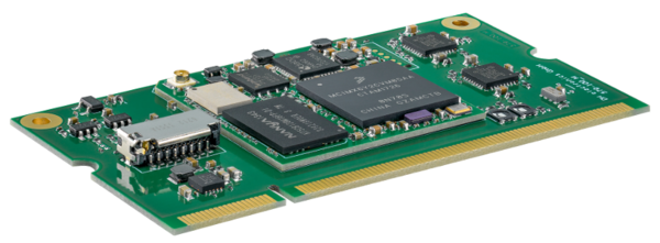
DHCOM iMX6ULL-D2: Difference between revisions
From Wiki-DB
Jump to navigationJump to search
| Line 19: | Line 19: | ||
* 128 - 1024 MByte NAND flash memory (8 bit bus width) or<br>4 - 16 GByte eMMC flash (8 bit bus width) | * 128 - 1024 MByte NAND flash memory (8 bit bus width) or<br>4 - 16 GByte eMMC flash (8 bit bus width) | ||
* 2 MB SPI boot flash | * 2 MB SPI boot flash | ||
* 128 - 1024 MByte DDR3- | * 128 - 1024 MByte DDR3-400 | ||
* On-board microSD card socket | * On-board microSD card socket (4 bit SDIO) <sup>[1]</sup> | ||
* LC display controller, 18 bit colors, 1366x768 pixels | * LC display controller, 18 bit colors, 1366x768 pixels | ||
* On-chip touch controller for 4-wire resistive touch screens | * On-chip touch controller for 4-wire resistive touch screens | ||
* 2x Ethernet controller 10/100 Mbit, IEEE1588 conform | * 2x Ethernet controller 10/100 Mbit, IEEE1588 conform <sup>[2]</sup> | ||
* USB 2.0 OTG high-speed | * USB 2.0 OTG high-speed | ||
* USB 2.0 host high speed | * USB 2.0 host high speed | ||
* Standard UART | * 2x Standard UART with hardware handshake support <sup>[3]</sup><sup>[4]</sup> | ||
* | * WiFi iEEE802.11b/g/n + Bluetooth v4.1 (BR/EDR/BLE) module on BGA <sup>[1]</sup><sup>[4]</sup> | ||
<br/><sup>[1]</sup> On module microSD socket is only available if WiFi is not mounted. | |||
<br/><sup>[2]</sup> The second SPI is only available, if the second ethernet is not mounted. | |||
<br/><sup>[3]</sup> CTS and RTS of the first UART is only available if second CAN port is not connected. | |||
<br/><sup>[4]</sup> The second UART is only available if Bluetooth is not used. This means WiFi/BT module 1DX is not mounted or module 1FX (only WiFi) is mounted. | |||
<br/><sup>[5]</sup> I²S lines are shared with JTAG. | |||
|valign="top" style="border: 0pt;" | | |valign="top" style="border: 0pt;" | | ||
* 2x CAN interface <sup>[3]</sup> | |||
* 2x CAN interface | * 2x SPI interface <sup>[2]</sup> | ||
* 2x SPI interface | * 2x I²C interface | ||
* 2x | * I²S Audio codec (1 x microphone, 1 x Line in, 1x Line out) <sup>[5]</sup> | ||
* I²S Audio codec (1 x microphone, 1 x Line in, 1x Line out) | * Real-time clock (I²C connection), low power temperature compensated | ||
* Real-time clock ( | |||
* 2x 10 bit analog input | * 2x 10 bit analog input | ||
* 2x 256 | * 2x 256 Bytes EEPROM with integrated MAC address | ||
* PWM channel | * PWM channel | ||
* | * 22 GPIOs (A-U + INT_HI_PRIO) | ||
* JTAG debug connection via FFC plug connector | * JTAG debug connection via FFC plug connector | ||
* Industrial temperature range (-40°C to +85°C) | * Industrial temperature range (-40°C to +85°C) | ||
Revision as of 14:38, 9 May 2019

|
Hardware
|
|
Software Support
Downloads
U-Boot Sources
Update-Kernel
Linux Kernel Sources / Prebuilt Kernels
- Mainline
- Vendor
Debian based root file systems
- Debian alone
- Based on Debian 6 "Squeeze" (2014-10-30)
Remark: Shellshock (CVE-2014-6271) is already fixed.
- Based on Debian 6 "Squeeze" (2014-10-30)
- Debian Qt5
- Based on Debian 8 "Jessie" + Qt5.9.1 (2017-10-06)
Remark: It must be used with i.MX6 Vendor Kernel 4.1.15
- Based on Debian 8 "Jessie" + Qt5.9.1 (2017-10-06)
- Based on Debian 8 "Jessie" + Qt5.7.1 (2016-12-19)
Remark: It must be used with i.MX6 Vendor Kernel 3.10.17
- Based on Debian 8 "Jessie" + Qt5.7.1 (2016-12-19)
Virtual Machine for Application Development
- Debian 8 "Jessie" VMware Image
Password for devel user: devel
Password for root user: root
- Debian 6 "Squeeze" VMware Image (PW: dhelectronics)
Password for devel user: devel
Password for root user: root
Mainline Linux 4.4.x eMMC update package
- i.MX6 Linux Kernel 4.4.60 with Debian Jessie Rootfilesystem
Extract files to USB stick and use stick to update i.MX6 Solo, DualLite or Quad
Code Examples for Userspace-Applications to Access SPI, I2C, GPIOs, and more
- Download Code Examples SPI, I2C, GPIOs, RTC, UART, Watchdog, and more
- Download C++ HAL class library for SPI, I2C, GPIO, UART and physical address space access
WEC7 DHHalLib.dll (function library)
- Download DHHalLib Library Version 1.3.0.0
- DHHalLib Demo App Source Code
- DHHalLib Demo App Binary File
- Download DHHalLib CSharp Demo Wrapper App
- Download DHHalLib CSharp Demo Wrapper App Binary File