Software: Difference between revisions
From Wiki-DB
Jump to navigationJump to search
No edit summary |
No edit summary |
||
| (One intermediate revision by the same user not shown) | |||
| Line 9: | Line 9: | ||
How to control a GPIO: | How to control a GPIO: | ||
:{| class="wikitable" | |||
|1. <code>''cd /sys/class/gpio''</code> | |||
|- | |||
|2. create new directory: <code>''echo 44 >export ''</code> | |||
|- | |||
|3. go into this directory: <code>''cd gpio44''</code> | |||
|- | |||
|4. show if GPIO is used as an input or an output: <code>''cat direction''</code> | |||
|- | |||
|5. change output to '1'=high: <code>''echo 1 >value''</code> | |||
|- | |||
|6. change GPIO to input: <code>''echo in >direction''</code> | |||
|- | |||
|7. show input value: <code>''cat value''</code> | |||
|} | |||
==PLD== | ==PLD== | ||
Latest revision as of 09:28, 8 August 2012
GPIOs
Mapping
In the following sheet you can find the GPIOs and their linux-number


Control
How to control a GPIO:
1. cd /sys/class/gpio2. create new directory: echo 44 >export3. go into this directory: cd gpio444. show if GPIO is used as an input or an output: cat direction5. change output to '1'=high: echo 1 >value6. change GPIO to input: echo in >direction7. show input value: cat value
PLD
Development Software
To write your own VDHL-code you can use the ispLEVER Classic Software from Lattice ([1]
You also need a programmer (e.g. HW-USBN-2A from Lattice) to deploy the VHDL-Code on your PLD.
After installing the software and the drivers for your programmer you can start a new project.
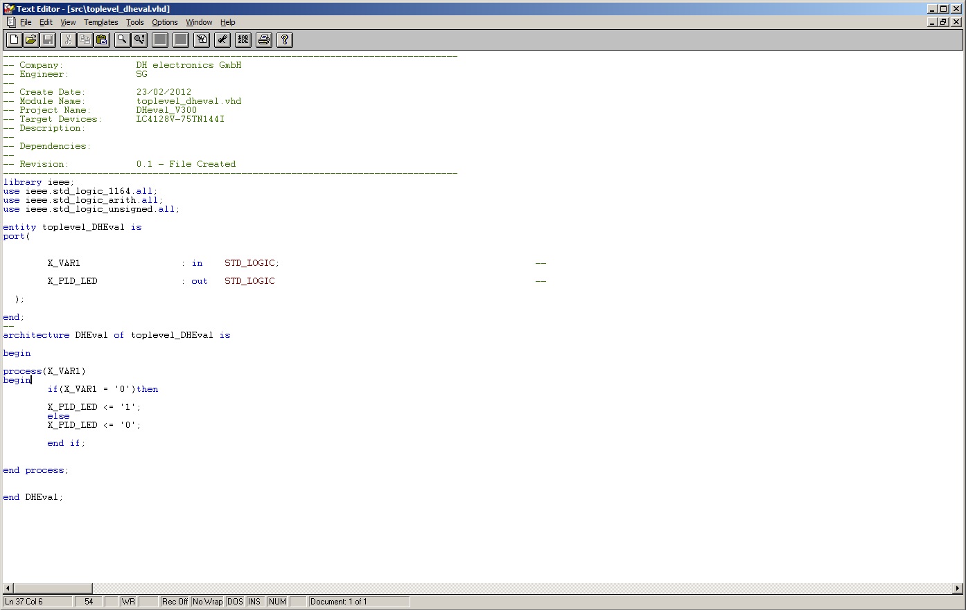
Programming example
You can find a demo-project here:media:PLD-demo.zip
You have to download the *.jed-File with the programmer to your PLD.
 In the constraint editor of ispLEVER you can define, which input X_VAR1 is.
 In this example GPIO E is defined as X_VAR1. If you define GPIO E as an
 output and set GPIO E high, the PLD LED should flash red.