DHSBC STM32MP13: Difference between revisions
From Wiki-DB
Jump to navigationJump to search
Ageisreiter (talk | contribs) |
Ageisreiter (talk | contribs) |
||
| Line 63: | Line 63: | ||
== Product Change Notifications (PCN) == | == Product Change Notifications (PCN) == | ||
* [[media:PCN_DHCOR-STM32MP13-001_R01_2025-08-12.pdf|PCN_DHCOR-STM32MP13-001_R01_2025-08-12.pdf (4Gbyte eMMC Samsung)]] | |||
== Downloads == | == Downloads == | ||
Revision as of 10:58, 14 August 2025
The DHSBC STM32MP13x board is the official DHCOR STM32MP13 reference design!

|
Introduction
Reference design for secure industrial IoT devices based on STM32MP13x
- Single Board Computer based on the solderable DHCOR STM32MP13
- Compatible with accessories from the Raspberry Pi© community
- Highlights: Bluetooth / WiFi, Dual GB Ethernet, Secure Boot, OP-TEE support
- Trusted Platform Module 2.0 available on request
- Mainline Linux support and active software maintenance
- Industrial product design with CE certification
- Guaranteed long-term availability of 10+ years
Technical Details
|
|
Product Change Notifications (PCN)
Downloads
Documentation
- NEW (for Hardware 719-300 / HS00047) Getting-Started with DHSBC STM32MP13 (R04)
- OLD (for Hardware 719-100 / HS00035) Getting-Started with DHSBC STM32MP13 (R03)
- DHCOR STM32MP13 User Manual R01 IMPORTANT: Please have a look at chapter 26. Hardware design checklist
Design Files
- DHSBC STM32MP13 Schematic
- DHSBC STM32MP13 Schematic --> NEW EMI optimized version! Use this as development template!
- DHSBC STM32MP13 3D STEP file
- DHCOR STM32MP13 Allegro/layout symbol
- DHCOR STM32MP13 3D STEP file
Software
DH Mainline based Linux
Useful instructions
Setup new board and install image files via USB (dfu and ums mode) / U-Boot recovery via DFU
How to connect to WiFi network with WPA2 PSK?
- Establish connection
$ wpa_passphrase "SSID" > /etc/wpa_supplicant.conf
- -> In the next step, please enter the password
$ rfkill unblock all $ ip link set wlansom0 up $ wpa_supplicant -B -i wlansom0 -c /etc/wpa_supplicant.conf $ udhcpc -i wlansom0
- Disconnect
$ ip link set wlansom0 down
Simple Bluetooth test
- Bring up bluetooth on the STM32MP13xx DHCOR SoM / DHSBC:
$ hciconfig hci0 up
- Make the STM32MP13xx DHCOR SoM / DHSBC discoverable to other BT devices:
$ hciconfig hci0 piscan
- Scan for other discoverable devices:
Scanning ...$ hcitool scan
- When the scan is now performed on a HostPC, the STM32MP13xx DHCOR SoM / DHSBC should be visible:
$ hciconfig hci0 up $ hcitool scan
- Scanning ...
DC:FE:23:12:34:56 dh-stm32mp13-dhcor-dhsbc
- To generate some traffic on the BT UART between SoC and BT chip, try e.g. L2 ping from hostpc:
l2ping DC:FE:23:12:34:56
        Ping: DC:FE:23:12:34:56 from E8:48:B8:11:22:33 (data size 44) ...
        44 bytes from DC:FE:23:12:34:56 id 0 time 11.44ms
        44 bytes from DC:FE:23:12:34:56 id 1 time 39.83ms
        44 bytes from DC:FE:23:12:34:56 id 2 time 39.25ms ...
- An interesting option to l2ping is -f, flood ping, which sends a lot of packets, that means a lot more traffic too:
l2ping -f DC:FE:23:12:34:56
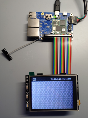
Add support for joy-it RB-TFT3.2V2 SPI display
- Add Device Tree oeverlay to u-boot.

=> setenv loaddtos '#conf-stm32mp135f-dhcor-dhsbc.dtb#conf-stm32mp13xx-dhcor-dhsbc-overlay-rb-tft32-v2.dtbo' => saveenv => saveenv
